Last Updated on October 29, 2023
Tension band wiring is a procedure based on the tension band principle and uses K-wires/screws and SS wires for fracture fixation.
Tension band wiring is commonly performed for patella and olecranon fractures. However, it can be done for many fractures including medial malleolus and greater trochanter fractures.
In fact, it can be done for fractures of bones which serve as ligaments or muscle attachments.
Tension Band Principle
In an eccentrically loaded bone, with a fracture perpendicular to the major plane of motion of the nearest joint, a device that absorbs the tensile forces and converts them to compressive forces is called a tension band.
For Tension Band Wiring,
- The bone must be eccentrically loaded.
- The fracture must be perpendicular to the major plane of motion of the nearest joint.
- The Tension Band Device must be placed on the tension surface of the bone
- The fracture must be caused by tension failure of the bone and must be intrinsically stable under compression and shear.
Contraindications to use of the Tension Band Wiring
Tension band wiring cannot be used in comminution as the fracture becomes intrinsically unstable against compression or shear.
Implants and Instruments for Tension Band Wiring
- K-wires 1.5/2mm
- Suture wire – The gauge of the wire could vary with the bone and the patient. Usually, 18 and 20 G are used )
- Orthopaedic Power Drill or Hand Drill
- Drill bit 2mm (Stainless Steel)
- Triple Drill sleeve (2mm) [wire guide]
- Pointed Reduction forceps
- Wire tightener
- Wire Bending Forceps
- Wire Cutter
- K wire Punch
- Mallet
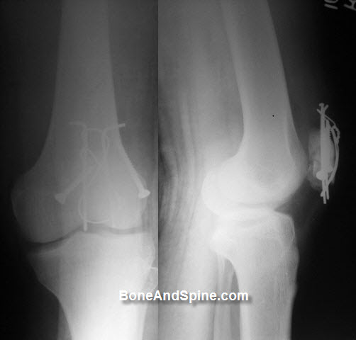
Tension Band Wiring of Olecranon Fracture

The tension band converts tensile forces on the posterior side of the olecranon into compression forces at the joint line.
The figure-of-eight wire loop lies on the posterior surface of the olecranon and acts as a tension band when tightened.
Procedure
Fracture Reduction
A transverse drill hole is made in the distal fragment approx. 2-4 cm from the fracture using 2mm drill bit. This serves as an anchoring point for the reduction forceps.
A 20G SS Suture wire is passed through this hole.
The fracture is reduced and held with pointed reduction forceps. The distal point of the forceps may be introduced into the previously drilled cortical hole.
Reduce the fracture and hold the reduction of the transverse olecranon fracture with small pointed reduction forceps.
Wire preparation and insertion
Approximately 40 mm distal to the fracture line and 5 mm from the posterior cortex, drill a hole through the ulna.
Prepare a 1.0 mm wire by making a loop approximately one third along its length.
Insert the wire through the drilled hole.
K-wire Insertion
The triple wire guide is used to insert a 1.6-2.0 K-wire from proximal [the head of the olecranon] to distal across the fracture site so that it engages the anterior cortex just distal to coronoid process.
Introduce the first 1.6 mm K-wire medially through. Aim the drill towards the anterior cortex, passing as close as possible to the joint. Leave enough space on the lateral side for the second K-wire.
A second K-wire is then introduced parallel to the first using the triple wire guide. The parallel ‘K’ wire allow axial compression. Both wires must engage the opposite cortex, to ensure stability against rotation and translation. (Fig.3)
Just after drilling the anterior cortex, drill the K-wire back approximately 1 cm. This is necessary as the proximal, bent ends of the K-wires will finally be hammered into the bone and the distal ends should not protrude into the anterior soft tissues.
Wire fixation
The previously inserted Stainless steel Suture wire is then passed in Fig. of 8′ fashion around these ‘K’ wires and through the triceps insertion. The wire is then tightened to ensure that all segments of the wire are equally and simultaneously tensioned. This is easily achieved by using loops placed symmetrically in the 2 long segments of the wire.
Alternatively, 2 separate segments of wire are used. One segment is passed through the bone (like the standard technique), and the other segment is passed around the ‘K’ wires and triceps insertion. This segment of wire is crossed and twisted with the distal segment, forming 2 symmetrically placed knots.
When tightening the wire loops, ensure that hat each end of the wire spirals equally – the twist should not comprise one spiral around a straight wire.
Cut the wire ends short.
The slack is then taken up by further twisting. Repeat this until the desired tension is achieved. .
By tightening the twist and the loop with two pliers simultaneously, the two fragments are drawn together such that the fracture is placed under compression.
Trim the twisted wire and turn both ends towards the ulna/olecranon in order not to irritate the soft-tissues later.
Sinking the K-wires
The tension is examined by flexing the elbow through its entire range of flexion.
The ‘K’ wires are cut obliquely, bent into a ‘U’ and impacted into the bone using the’ K’- wire punch. This prevents “backing out” of the K-wires to prevent backing out and skin irritation.
Confirm fracture stability and range of motion, including supination-pronation.
As an alternative, one intramedullary screw [6.5 mm cancellous screw with a 32 mm thread and a washer inside the canal.] or two intramedullary K-wires may be used instead of the two K-wires penetrating the anterior cortex.
Intramedullary K-wires have a greater risk of backing out.
The wound is closed in layers.
Tension Band Wiring for Patella Fractures
Tension band wiring is indicated for both transverse and comminuted fractures of the patella. It is done using K-wires or 4 mm cancellous lag screws are incorporated into a figure of 8 wire.
Procedure
Exposure
- Supine position
- Midline incision
- Expose the entire anterior surface of the patella, the quadriceps, and patellar tendon
- Identify the fracture configuration and any defect in the extensor mechanism
- Reduce the fracture with two large towel clips or patella reduction clamp
- Check for articular reduction by assessing the posterior aspect of the patella to look for step off.
K-wire Insertion
Insert two parallel 2.0-millimeter smooth K wires from an inferior to superior direction until they come out of the superior pole. Knee flexion may help during K wire insertion [ but it also puts stress on fracture fragments]. So should be done carefully.
Wires can be inserted from superior to inferior direction too.
The wires should be inserted slightly anterior to the mid-point in an anteroposterior plane to avoid deep embedding of wires in the substance of the quadriceps and patellar tendons,
Passage of SS Wire and Tension Band Wiring Assembly
Loop an 18-gauge wire directly behind the K wires superiorly, make a figure of 8 by crossing the wire ends on the anterior surface and then loop the wire again behind the K-wires inferiorly. [ It can be done in from inferior to superior direction too.]
The wires should pass thru the anterior portions of the quadriceps and patellar tendons just posterior to the K wires
The two ends of the wires are brought anteriorly over the surface of the patella, and each medial and lateral side is twisted and tightened.
K-wire Trimming
Inferiorly, bend each end of the K wires 180 deg, cut short, and impact into the patellar bony surface. Superiorly twist the K wires 180 degrees and cut them short, but do not impact them
Some surgeons just shorten the K-wires inferiorly and do not bend them but others bend both the superior and inferior ends of the K wires in order to prevent K wire migration;
Excess of SS wire is cut and the rest is buried under the tissue so as not to irritate the skin.
Following hardware insertion, the extensor retinaculum is repaired followed by skin sutures.